

Links
Tags
Creators
Details
1.5.0
Compatibility
Changes
CircuitSim 1.5.0
The 1.5.0 release adds two new analysis capabilities — loop-gain stability (.STB) and Monte Carlo — plus in-world operating-point annotation on the K key, three new component blocks (Transformer, Transmission Line, Loop Probe), and direct support for KiCad and LTspice model libraries. It also brings an LTspice-style Measurement Builder, a pre-simulation circuit linter, and a netlist viewer.
New Components
Transformer — a 2×3 coupled-inductor block with one primary and one secondary winding (west pins = primary +/−, east pins = secondary +/−). The edit screen sets the coupling factor k (0 < k ≤ 1), primary inductance Lp, and secondary inductance Ls — all three sweepable with Param-block expressions. Each winding has an editable series resistance (default 1 mΩ; set 0 for a fully ideal winding). Note: the windings are galvanically isolated, so the secondary side needs its own DC path to ground (a resistor is enough) or ngspice will refuse to solve.
Transmission Line — a 2×3 two-port block with two modes selected in its edit screen: lossless (characteristic impedance Z0 plus either a delay TD or a frequency F with normalized length NL; a freshly placed line defaults to Z0=50, TD=10ns) and lossy LTRA (per-length R, L, G, C plus the line length LEN; valid parameter combinations are RLC, RC, LC, and RG). All parameters accept {param} expressions for parametric sweeps.
Loop Probe — a 2-pin block you drop in series inside a feedback loop. In every normal analysis it behaves as a transparent 0 V short and changes nothing; its purpose is the new .STB analysis. Orientation matters: the front face points toward the amplifier output — if your loop-gain plot looks inverted (tiny or negative dB where you expect gain), rotate the probe 180°.
Inductor series resistance — standalone Inductor blocks gained an optional series-resistance field. Existing inductors stay ideal, but an ideal inductor straight across an ideal voltage source makes the DC operating point unsolvable ("singular matrix"), and a small Rser is the cure.
New Analyses
.STB stability (loop-gain) analysis — a new STB tab in the Simulate block, equivalent to Cadence Spectre's stb analysis. Place a Loop Probe in the feedback path, set the frequency range (same fields as AC), and run. The mod performs full Tian dual-injection — two AC runs (voltage and current injection) combined into the true loop gain — so the result is correct even at low- or high-impedance breaking points. You get Bode plots of loop-gain magnitude (dB) and phase (degrees) with phase unwrapping so the −180° crossing is visible, plus DC loop gain, unity-gain frequency (GBW), phase margin, and gain margin reported directly.
Monte Carlo — a new "Monte Carlo runs" + "seed" row in the Simulate dialog, available for OP, AC, DC, and TRAN. Randomness comes from ngspice statistical distributions in Param blocks (Rv = gauss(10k, 0.05, 3), plus agauss, unif, aunif, limit) and/or the new per-component tolerances below; every run re-rolls the values. AC/TRAN/DC runs overlay all iterations in the graph screen, OP runs plot each probe against run number, and every measured scalar (phase margin, GBW, ...) gets a mean / standard deviation / min / max summary in chat. A fixed seed makes runs reproducible; a blank seed picks a random one and tells you what it was. Capped at 300 runs.
Component tolerances — ideal resistors, capacitors, and inductors now have a "Tolerance (%)" field in their edit screens, shown on the floating label (e.g. "1kΩ ±5%"). During Monte Carlo each toleranced device gets its own independent Gaussian draw with ±tolerance = 3σ; outside Monte Carlo the nominal value is used, so normal simulations stay deterministic.
Histograms — graph screens gained a "Hist" toggle that re-bins the active curves' values into overlaid histograms — the natural way to look at Monte Carlo spreads.
Operating-Point Annotation
K-key annotation — after an .OP run, press K to float up to 4 chosen parameters over every device in the world: node voltages, currents, and for MOSFETs the full internal parameter set. "Edit Shown OP" picks which parameters are shown, per device type, from a grid of everything ngspice reports (IC MOSFETs expose ~65 parameters). Derived MOSFET figures of merit are computed for you and listed next to gm: gm/id, gm/gds (intrinsic gain), and fT = gm/(2π·cgg). Parametric and temperature OP sweeps produce one annotation frame per swept value, with < / > arrows to step through them and watch the bias points move.
Subcircuit OP projection — while K annotation is active, any Subcircuit chip with .OP data floats a shrunk 3D copy of its inner circuit above the block, with each internal device's operating point annotated — you can see the bias of every transistor inside a chip without unpacking it. Note: chips converted before 1.5.0 don't carry the required device map; re-convert them once.
Subcircuit 3D preview — the Subcircuit screen itself now renders a 3D preview of the chip's inner circuit, so you can see what a chip contains before placing it.
Model Library Support
Two new compatibility modes in the Simulate block make real vendor models usable directly:
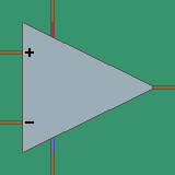
KiCad mode (ki) — point the paths box at KiCad's model libraries; it pre-fills the installed KiCad's built-in Simulation_SPICE.sp automatically, and the runner enables the same PSpice+LTspice translation KiCad itself uses. Discrete MOSFET/BJT/diode blocks auto-detect whether the library defines a .model card (e.g. VDMOS power FETs) or a .subckt macromodel (e.g. KiCad's BJTs) and emit the right SPICE device either way. The Amplifier block's pin order matches KiCad's 5-pin op-amp convention (IN+ IN− VCC VEE OUT) directly.
LTspice mode (lt) — pre-fills the installed LTspice's component databases (standard.dio / standard.bjt / standard.mos — thousands of diode, BJT, and VDMOS cards) and reads vendor .sub/.lib macromodels. UTF-16 library files — which ngspice otherwise silently loads zero models from — are transcoded automatically, and LTspice TABLE(...) B-sources are rewritten to ngspice pwl(...). Known limits: ADI-encrypted models (<Binary File>) and OTA-based macromodels (UniversalOpAmp2, newer ADI op-amps) only run inside LTspice itself.
Also fixed in this area: ngspice's XSPICE code models (used by translated PSpice switches) now load reliably when ngspice is found via PATH.
Simulation Workflow
Measurement Builder — a "Measure…" button in the Commands block opens an LTspice-style editor with three tabs: Measure (build a single meas line from a form), Functions (expression palette for derived plots), and Presets (rise/fall time, propagation delay, period, overshoot, THD, slope-at-point, and a full AC amplifier report). Signal fields have a picker listing your live probes, sources, and plot names, and a Test button runs your configured analysis right there and shows the measured values before you save.
View Netlist — a button in the Simulate block generates and displays the complete SPICE netlist without running the simulation, with one-click Copy. Useful for debugging or moving a circuit to desktop ngspice.
Circuit linter — before each run the mod now checks for the classic silent killers and explains them in plain language: no Ground block placed, floating nodes (a wire to nowhere), and nodes with no DC path to ground (reachable only through capacitors or current sources).
Dual-waveform plots — a plot screen can now show two different waveforms together on one plot.
Other Changes
- Simulations no longer hand you a written book with raw output after every run; results go to chat and the graph screens.
- Fixed the Simulate block forgetting analysis parameters when switching between analysis types in its edit screen.
- The separate subcircuit-projection key was removed — projections now ride along with the K annotation automatically.
- New inventory item icons for the VCVS, VCCS, Amplifier, and Subcircuit blocks.